Thrust Vectoring Mechanism
M Class Solid Rocket
Mechanical Design Course Project
A final, comprehensive design project incorporating full CAD assembly, FEA on multiple components, and dynamic analysis through Solidworks Motion. The system went through multiple revisions advised by both analysis results and course feedback culminating in a final design with renderings.

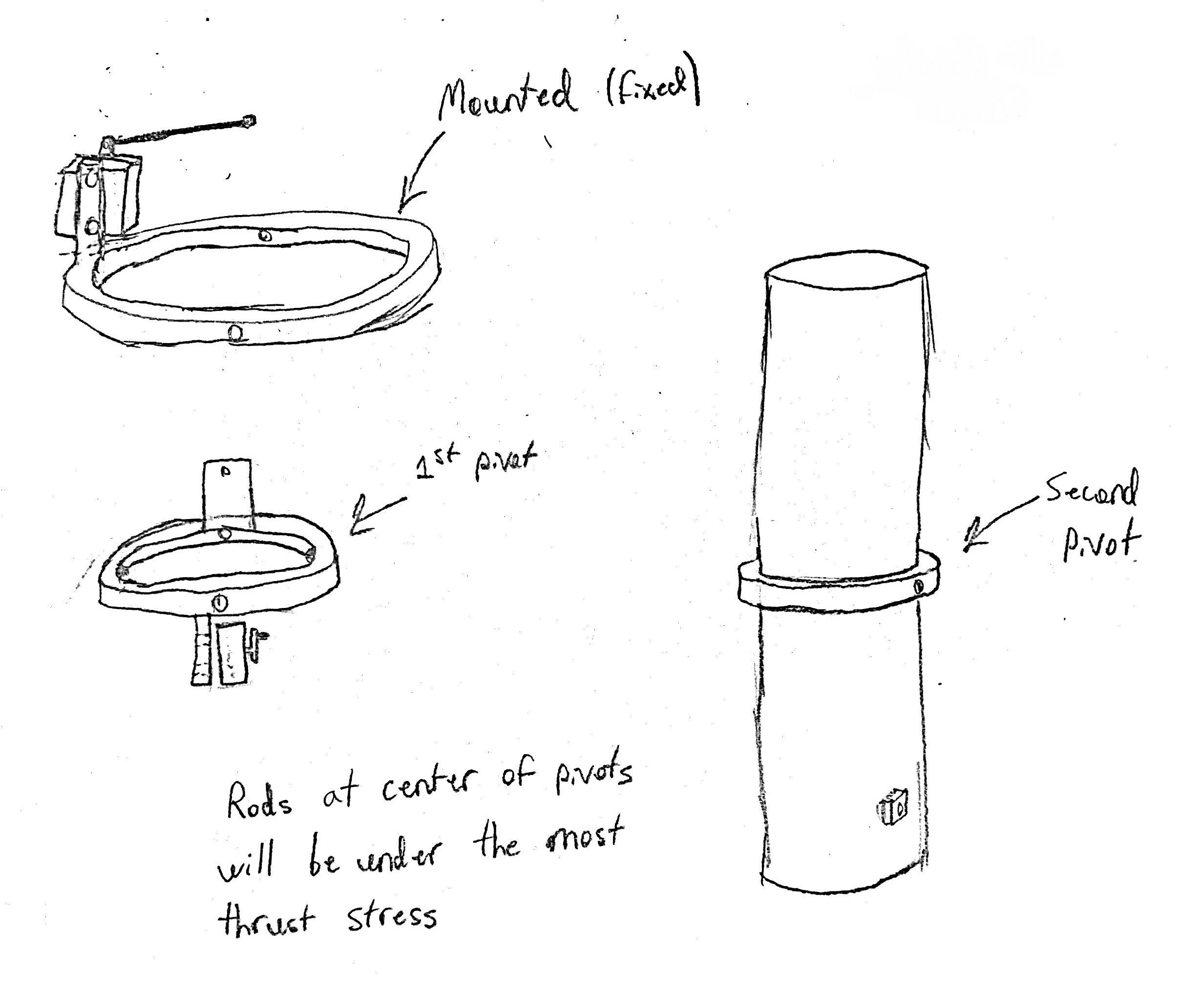
Initial sketch of the pivoting system. A series of three rings with two pivot axes allow the motor to move pitch and yaw. The outermost ring is fixed to the vehicle's interior while the innermost ring is fixed to the motor tube that in turn constrains the motor in a traditional high powered model rocket. Two small servos control the motor's motion via music wire links.
CAD of the secondary assembly above the pivot mechanism. This upper ring holds three cams that when turned form a solid structural link between the motor tube and the vehicle body, preventing any unintended pivoting. This feature is useful in the first moments of flight while the rocket is still affixed to the launch rail and no thrust deviations should occur. In addition to the cams, this ring also supports the cam driving motors and a passthrough for wires from all servos on this ring and the pivot mechanism below.

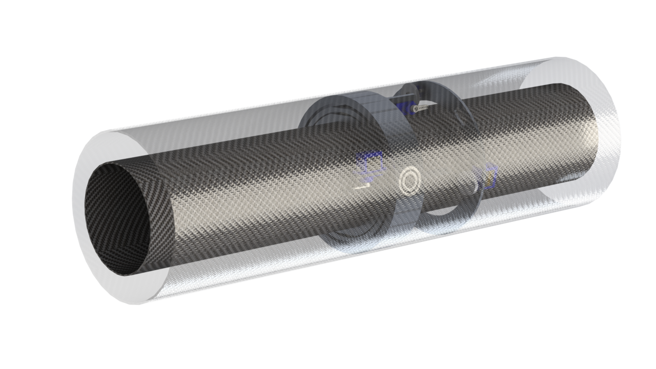
Final render of the entire assembly using PhotoView 360. The outer body tube has been made translucent for enhanced viewing of the internal parts that make up the bulk of the assembly.
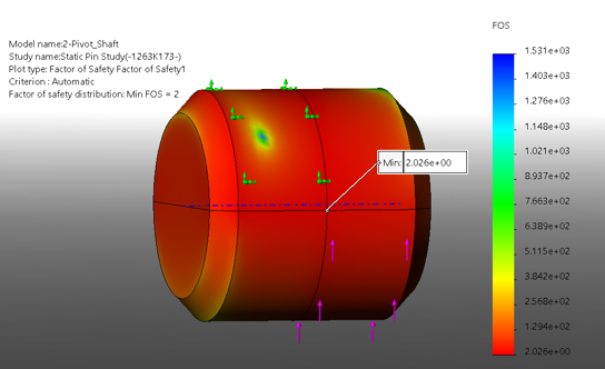
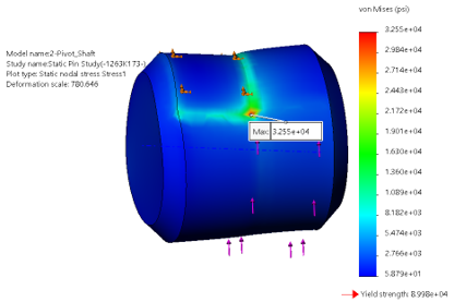
Results of the FEA for the pivot shafts. These shafts had to be designed to comfortably take all of the 419 pounds of force the motor would deliver at its peak force. That force would be divided between two pivots on opposite sides of each ring however multiple iterations of the design needed to be explored in order to raise the FOS to an acceptable level. I looked into different materials in addition to raising the diameter of the pins and a combination of both was needed in the end to take the expected load.
These FEA studies were undertaken after I drew up free body diagrams and confirmed that the forces I was planning to feed into the FEA were correct. These analyses were also backed up by motion analysis through Solidworks Motion to check for any additional dynamic effects not picked up from a purely static analysis.

